Plate IFig. 1 · Woodcut
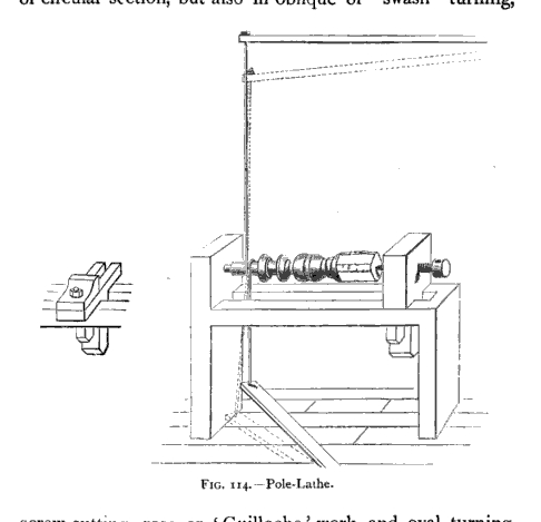
The pole-lathe
Fig. 114. Treadle, cord, and spring-pole. The wood turns because the pole returns.
C. P. B. Shelley, Workshop Appliances, 1897. Public domain.
Anvil & BoughCentral Alabama’s Maker Place
AnvilandBough
Anvil & Bough
Central Alabama’s Maker Place
The plates · Pictures
These are historical documents, bound into the same catalog as the diagrams: old print of making, a machine drawing from the engineer’s book, and the Pratt & Whitney shop floor about the last war.
Plate IFig. 1 · Woodcut
Fig. 114. Treadle, cord, and spring-pole. The wood turns because the pole returns.
C. P. B. Shelley, Workshop Appliances, 1897. Public domain.
Plate IIFig. 2 · Woodcut
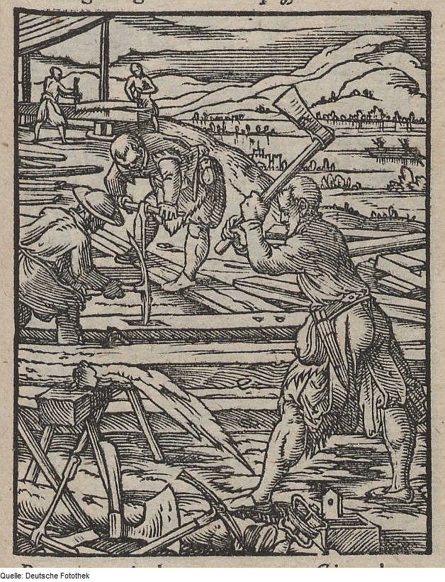
Der Zimmermann. The yard before the shop: axe, auger, frame-saw.
Jost Amman, Das Ständebuch, 1568. Deutsche Fotothek. Public domain.
Plate IIIFig. 3 · Woodcut
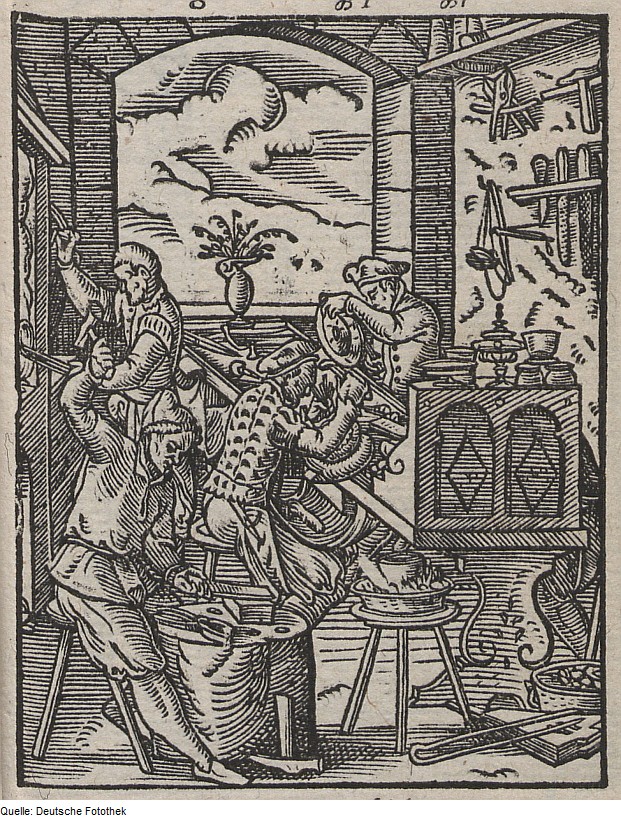
Der Goldschmied. Hammer, punch, and the small work that stays on the table.
Jost Amman, Das Ständebuch, 1568. Deutsche Fotothek. Public domain.
Plate IVFig. 4 · Drawing
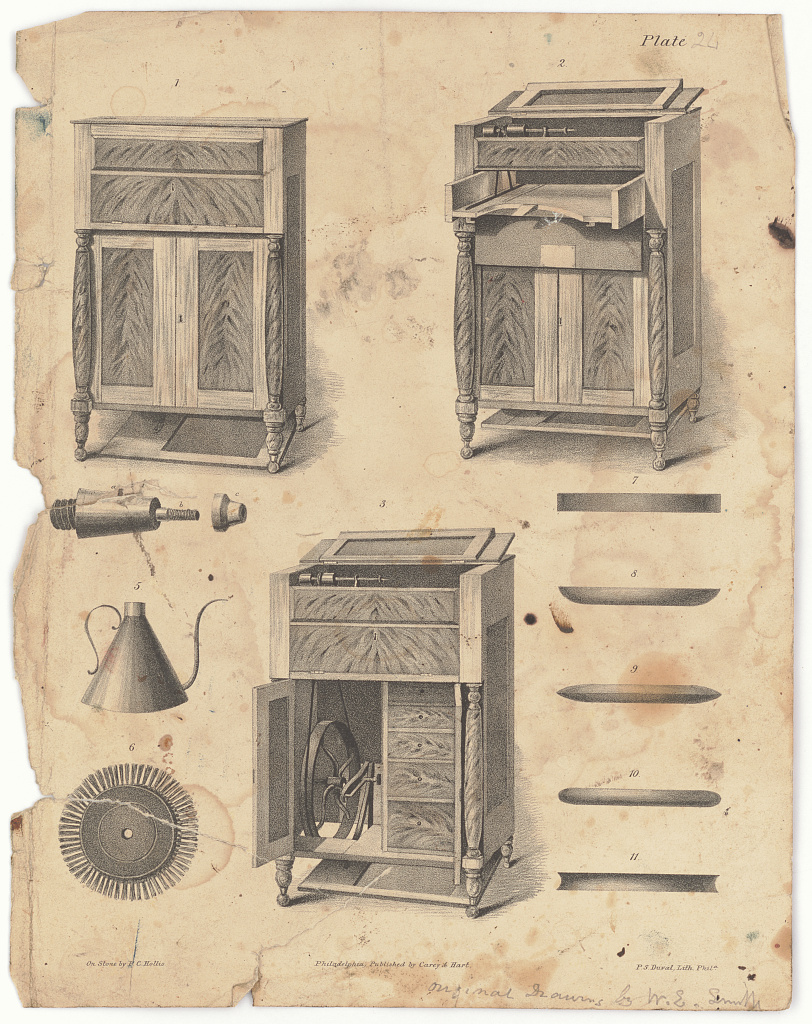
Plate 24. Closed as furniture; opened, a treadle, flywheel, and bed.
P. C. Hollis, on stone; P. S. Duval, Lith., Philadelphia, 1844. Library of Congress. Public domain.
Plate VFig. 5 · Drawing
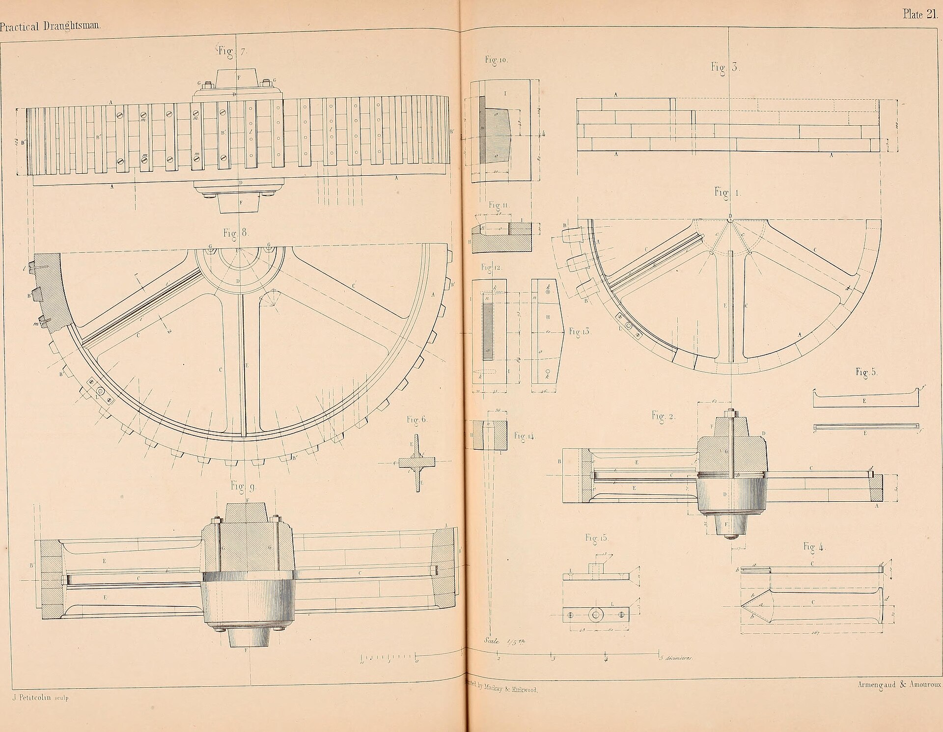
Plate 21. Hub, spokes, rim, and the section that tells the tooth.
Armengaud & Amouroux, The Practical Draughtsman’s Book of Industrial Design, 1854. Public domain.
Plate VIFig. 6 · Drawing
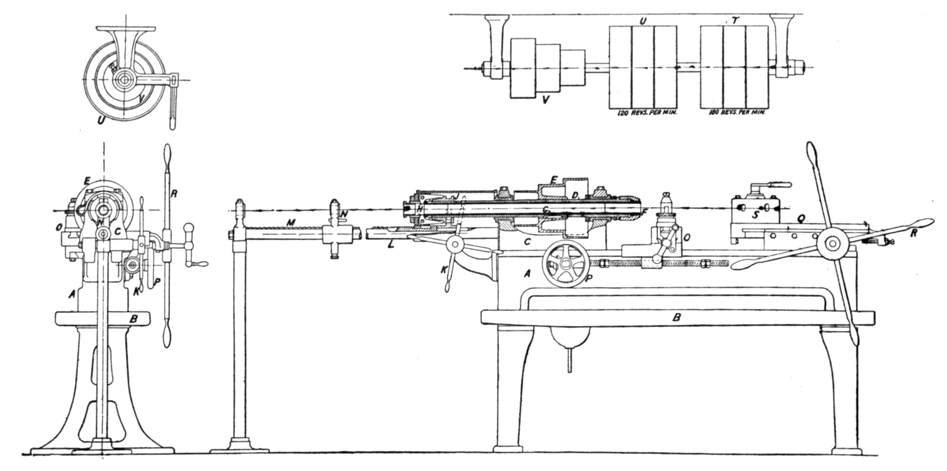
Bed, headstock, and the line-shaft speeds written on the drawing: 120 and 180.
Encyclopædia Britannica, 11th ed., 1911, “Tool.” Public domain.
Plate VIIFig. 7 · Photograph
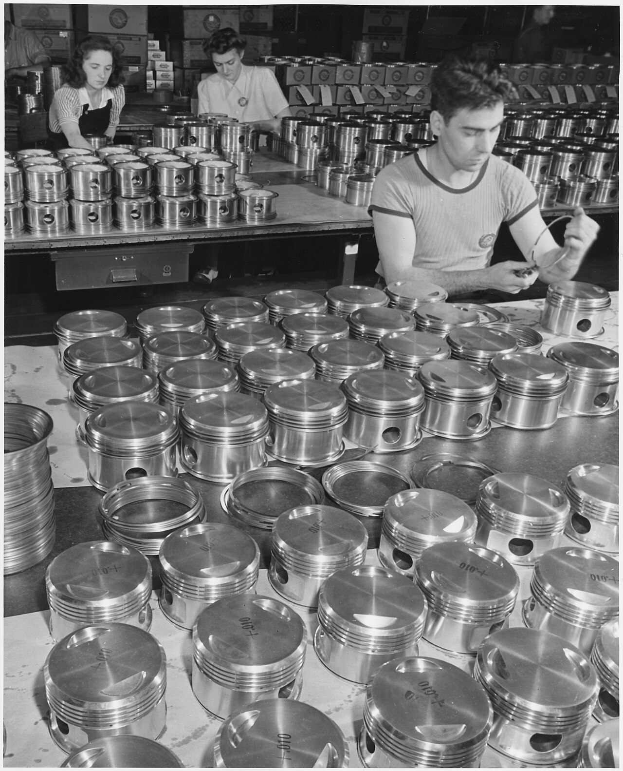
Pistons laid out by the hundred. The ring is tried by hand before it is left on the piston.
U.S. Office of War Information, June 1942. National Archives (NARA 195473). Public domain.
Plate VIIIFig. 8 · Photograph
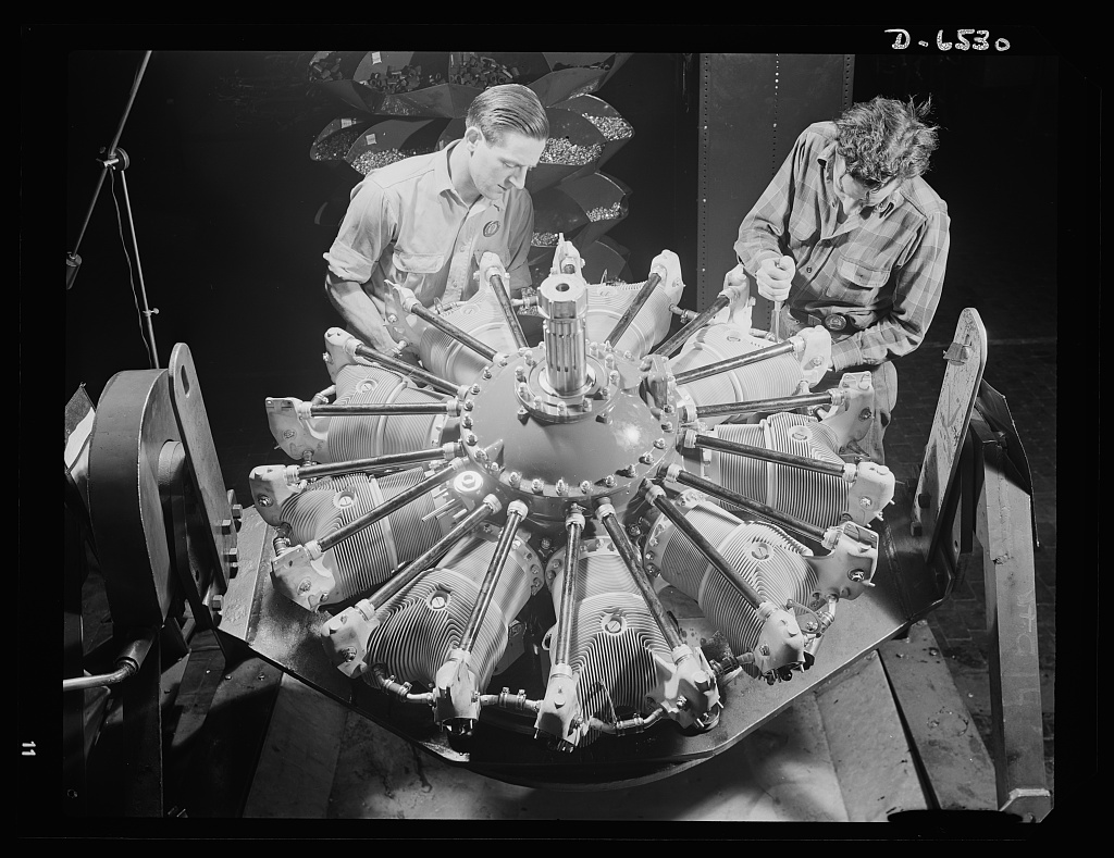
Single-row intake pipes going onto a new engine. The plant is Pratt & Whitney Aircraft.
Andreas Feininger, June 1942. FSA/OWI, Library of Congress. Public domain.
Plate IXFig. 9 · Photograph
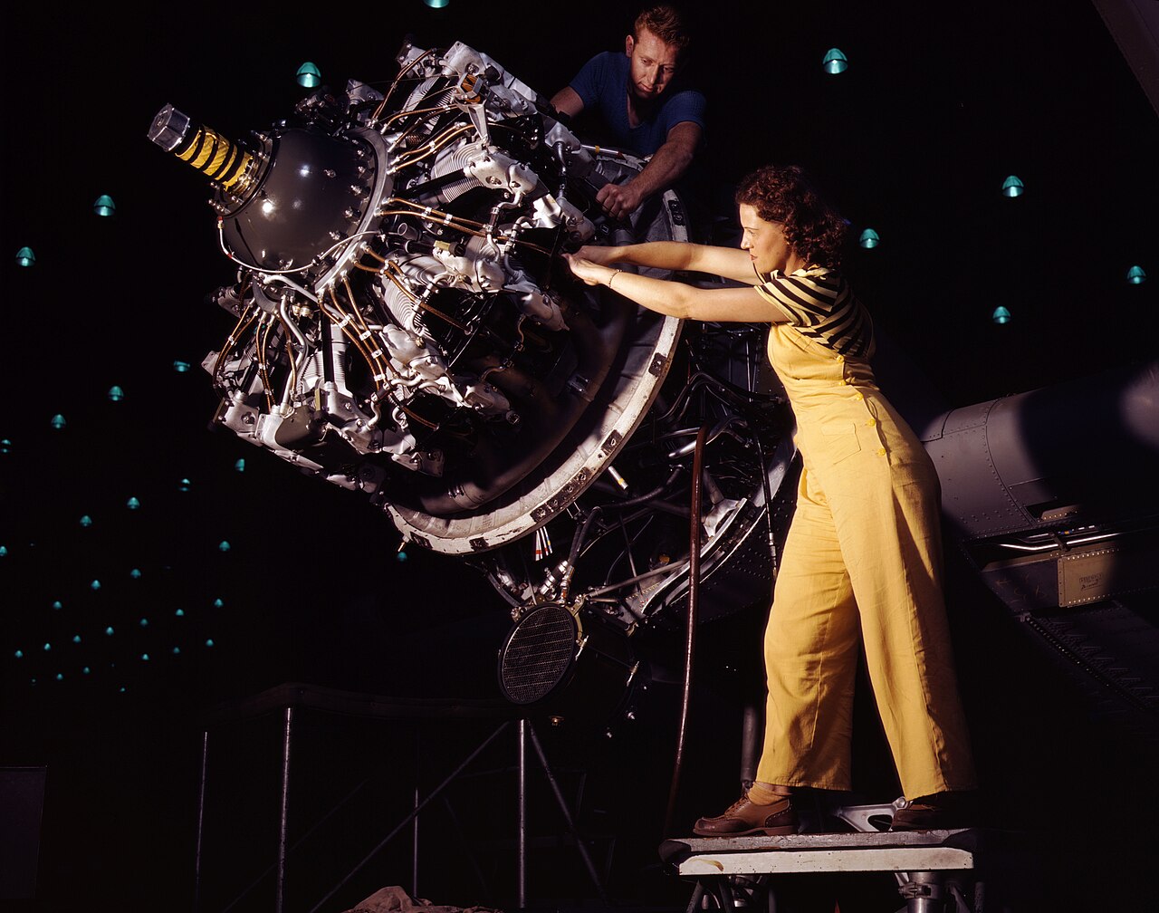
R-1830 Twin Wasp, fourteen cylinders, being trained onto the nacelle.
Alfred T. Palmer, October 1942. FSA/OWI, Library of Congress. Public domain.